> DDS Function Signal Generator
> Digital Multimeters
> Distortion Analyzer
> Four Probe experiment
> Function Generator
> IC Testers
> LCR Meters
> Oscilloscopes
> Power Supplies
> Pulse Wave Frequency Meter
> Signal / Function Generator
> Storage Oscilloscopes
> Two Probe Setup
> Withstand Tester
> General Physics Equipments
 
- Digital Micro Volt Meter
- Digital Nano Ammeter
- Digital Pico Ammeter
- Digital Gaussmeter
- Magnetic Field Measurement Apparatus
- Study of Dieletric Constant & Curie Temp of Ferroelectric Ceramics
- e/m Experiment
- Planck’s Constant by Photoelectric Effect
- Determination of Planck’s Constant by means of LED’s
- Frank Hertz Experiment
- Ionisation Potential Set-up
- Measurement of Magnetoresistance of Semiconductors
- Two Probe Method for Resistivity Measurement of Insulators
- Electron Spin Resonance Spectrometer
- Study of Thermoluminescence of F-centres in Alkali Halide Crystals
- Hall Effect in Metals
- Dependence of Hall Coefficient on Temperature
- Apparatus for the Measurement of Susceptibility of Paramagnetic Solution by Quinck's Tube Method
- Apparatus for the Measurement of Susceptibility of Solids by Gouy’s Method
- Magnetic Hysteresis Loop Tracer
   
> TEKON INSTRUMENTS
  - T100 Network Cable Detector
  - T550 Power Quality Analyzer
  - T560 Power Quality Analyzer
  - T600 Txr Turn to Ration
  - T610 Txr Analyzer
  - T650 ESS Diagnostic
  - T700 Ind. Robot Diagnostic
  - T800 EV-HEV Diagonstic


General Physics Equipments
Magnetic Hysteresis Loop Tracer
   
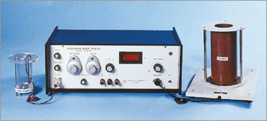
  • Measures magnetic parameters accurately
  • Demagnetisation, eddy currents and sample cross-sectional area have been accounted for
  • Capable of detecting the number of magnetic phase present in a sample

Introduction

A precise knowledge of various magnetic parameters of ferromagnetic substances, viz. coercivity, retentivity, saturation magnetisation and hysteresis loss, and ability to determine them accurately are important aspects of magnetic studies.

The information about the aforementioned properties can be obtained from a magnetic hysteresis loop which can be traced by a number of methods in addition to the slow and laborious ballistic galvanometer method. Among the typical representatives of AC hysteresis loop tracers, some require the ring form of samples while others can be used with thin films, wires or even rock samples. Ring form samples are not always practically convenient to make while in others demagnetisation effects sometime become quite important.

The present set-up can accept the samples of thin wires of different diameters. The demagnetisation effects, different diameters of samples and eddy currents (due to the conducting property of the material) has been taken into account within the design

Design Principle

When a cylindrical sample is placed coaxially in a periodically varying magnetic field the magnetisation in the sample also undergoes periodic variation. This variation is packed up by a coil placed coaxially with the sample.

For the uniform field Ha produced, the effective field H acting in the cylindrical sample will be

H = Ha-NM            or

H = Ha-NJ/µo  ...............................( 1 )

where M is magnetisation, N is normalised demagnetisation factor including 4p and J is the magnetic polarisation defined by

B = µoH + J

with B = m H or m 0(H+M) as magnetic induction. The signal corresponding to the applied field, Ha can be written as

e1=C1Ha ...................................... (2)

where C1 is a constant

Further the flux linking with the pick-up coil of area Ac due to sample of area As will be

Φ = µo(Ac-As)H' + AsB.

which under certain conditions reduces to

Φ = µoAcH + AsJ

The signal induced in the pick-up coil (e2) will be proportional to df/dt which after integration yields.

e3 = C3Φ = C3µoAcH + C3AsJ ........(3)

Solving (1), (2) and (3) gives

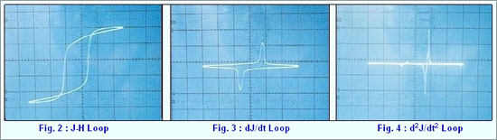
Based on these equations the electronic circuit has been designed to give values of J and H and hence the hysteresis loop. Further different magnetic phases present in the sample may also be identified by electronically manipulating the pick-up signal.


Basic Circuit

The magnetic field has been obtained with an ac mains driven multilayered solenoid. This magnetic field has been calibrated with a Hall Probe for uniformity and correspondence with the magnetic field calculated through ac current passing in the solonoid. A small resistance in series with the solenoid serves the purpose of taking a signal e1 corresponding to H2 (corresponding to dJ/dt) is taken from the pick-up coil placed at the centre of the solenoid and contains the sample. It is integrated and corrected for phase. This signal is then subtracted from the reference signal e1 and amplified to give the signal corresponding to J. The e1 signal is also subtracted from 3e3 in correct ratio (to account for demagnetisation and area ratio) and amplified to give signal corresponding to He2 is also passed through the differentiator for getting signal corresponding to d2J/dt2 which is used for phase identification.

Applications

The following magnetic parameters can be measured by this set-up:

  • Coercivity
  • Retentivity
  • Saturation magnetisation
  • Various magnetic phase identification
  • Hysteresis loss

The equipment is complete in all respect, including a set of samples (wires of Nickel, and different grades of iron etc.). A Cathode Ray Oscilloscope will however be required.


* Products not listed can be ordered as per request.
* Model number may subject to change without intimation